Телефонный номер:0086-0577-61731588
Факс:0086-0577-61731588
Сотовый телефон:+86 18072180777
Wechat:+86 18072180777
Веб-сайт:ru.china-relay.com
Промышленная зона Чжигуан, город Лю, Юэцин, Чжэцзян, Китай
Power supply voltage: 220VAC 50/60Hz;(2) 100-240 vac/DC
Allowable voltage variation range: 90-110% of supply voltage
Power consumption: below 8VA
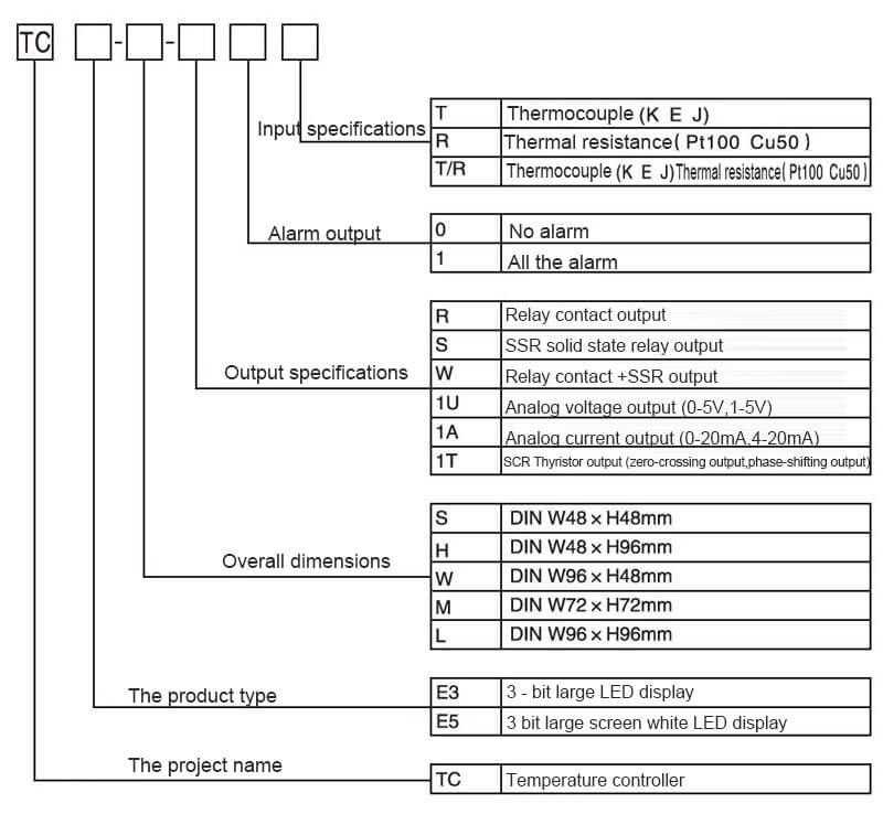
Input specification: Thermocouple :K, E, J
Thermal resistance :Pt100 Cu50
Display accuracy :±0.5%
Input specification: relay 250VAC 5A one on one off
SSR 12VDC±2V 20mA or less
Analog voltage output (0-5V, 1-5V)
Analog current output (0-20mA, 4-20mA)
SCR Silicon controlled output (zero crossing output, phase shifting output)
Обратите внимание на безопасность
※ «Обратите внимание на безопасность» означает безопасное и правильное использование продукта для предотвращения возникновения опасных несчастных случаев. Обратите внимание на следующее содержание.
※ Внимание Безопасность можно разделить на две части: «предупреждение» и «внимание». Смысл в следующем:
⚠ предупреждение, например, нарушение этого правила может привести к серьезным травмам или смерти.
⚠ внимание, например, нарушение этого правила может привести к легким травмам или повреждению продукта.
⚠предупреждение
1. двойные защитные устройства защиты должны быть установлены перед использованием машин (таких как ядерная энергетика, медицинское оборудование, корабли, транспортные средства, железные дороги, авиация, оборудование для сжигания, предохранительные устройства и устройства предотвращения / кражи стихийных бедствий), которые имеют значительную влияние на жизнь и имущество человека.
В противном случае это может привести к пожару, травмам или материальному ущербу.
2.Панель должна быть установлена при использовании.
В противном случае существует опасность поражения электрическим током.
3.Не выполняйте работы по техническому обслуживанию при включенном питании.
В противном случае существует опасность поражения электрическим током.
4.Пожалуйста, подтвердите номер терминала перед подключением.
Это могло вызвать пожар.
5.Продукт не может быть изменен, кроме обслуживающего персонала компании.
В противном случае это может привести к поражению электрическим током или возгоранию.
⚠заметка
1.Не используйте этот продукт на открытом воздухе.
В противном случае срок службы изделия сократится или произойдет поражение электрическим током.
2.При подключении входного конца источника питания к выходному концу реле используйте кабель AWG 20 (0,50 мм2) и сохраняйте крутящий момент винта 0,74 ~ 0,90 Н · м.
Плохой контакт может вызвать пожар.
3.Пожалуйста, используйте продукт в соответствии с номинальными характеристиками.
В противном случае срок службы изделия сократится, и возникнет опасность возгорания.
4. Используйте нагрузки меньше допустимой мощности контактов реле.
В противном случае это вызовет плохую изоляцию, соединение контактов, плохой контакт, повреждение реле, возгорание и так далее.
5. Не используйте воду или органический растворитель при чистке и протирайте сухим полотенцем.
Это может привести к поражению электрическим током или возгоранию.
6.Избегайте использования продукта в легковоспламеняющихся, взрывоопасных, влажных, прямых солнечных лучах, тепловом излучении, вибрации и других местах.
Это может привести к возгоранию или взрыву.
7.Не допускайте попадания пыли или остатков кабеля в изделие.
В противном случае это может привести к возгоранию или повреждению продукта.
8.После подтверждения полярности клемм правильно подключите проводку термопары.
В противном случае возможно возгорание или взрыв.
9.Для усиления изоляции используйте источник питания, обеспечивающий повышенную изоляцию.
Код модели
 Название каждой части
Внешний размерный чертеж
Функциональные характеристики
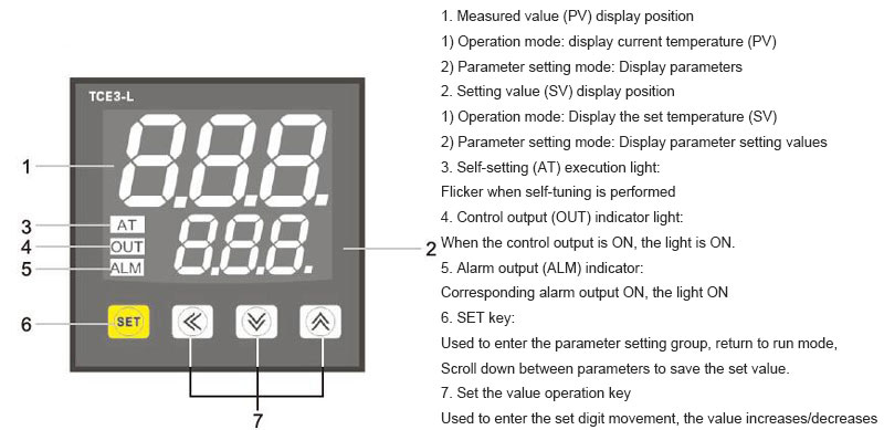
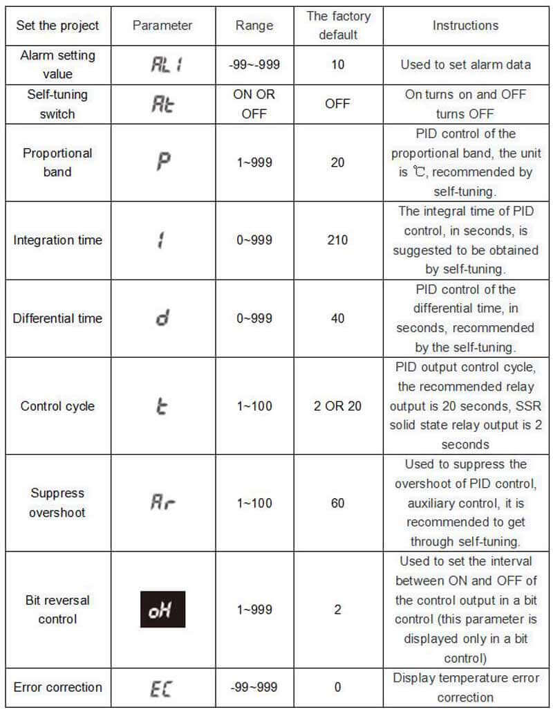
1.Самонастройка[ ]
]
Самонастройка ПИД-регулятора - это функция контроллера температуры для расчета параметров ПИД-регулирования путем измерения тепловых характеристик и времени теплового отклика объекта управления, и с помощью этой функции можно реализовать автоматическую настройку параметров для обеспечения высокоскоростного и стабильного управления.
※ При самонастройке система отопления должна быть в рабочем состоянии, а измеренное значение PV должно быть ниже установленного значения SV.
※Когда параметр режима управления находится в состоянии "
 ", отображается переключатель самонастройки [
 ].
].
※ Установите переключатель самонастройки[ ] в состояние "
 ", и световой индикатор AT начнет мигать, указывая на то, что состояние самонастройки было введено.
※ Во время выполнения автонастройки, все группы параметров и значение параметров SV будут заблокированы. Если вы хотите прервать самонастраиваемости вручную, установите переключатель самонастройки [ ] в состояние "
 ".
".
※Если во время самонастройки появляется код неисправности " "или"
"или" "он автоматически прерывается.
※После завершения самонастройки индикатор AT перестанет мигать, а параметры полученные в результате настройки, будут сохранены автоматически , И возвратит состояние управления для продолжения работы с новым изопараметром
 .
.
※Прерывание самонастройки, параметры  не будут изменены.
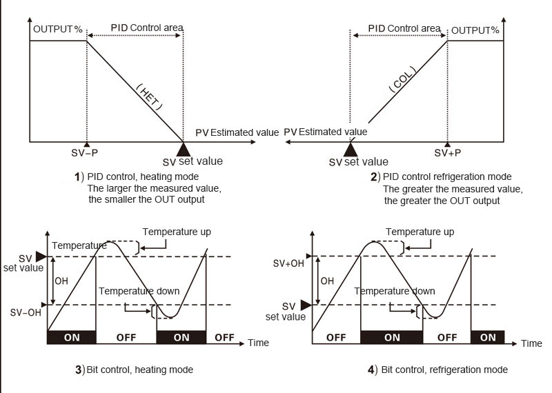
2.Режим управления
Параметры режима управления в состоянии "
 ", текущий режим ПИД-управления, если в состоянии "
 ", это состояние управления битами.
3.Подавить перерегулирование [ ]
]
Для ПИД-управления регулировка подавления перерегулирования: чем больше установленное значение, тем быстрее нагрев, легко перерегулировать; чем меньше значение настройки, тем медленнее нагрев и нелегко перерегулировать. Заводское значение по умолчанию - 60. Рекомендуется получить установить значение с помощью самонастройки ПИД.
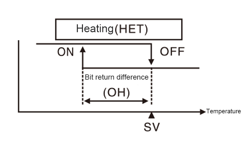
4.Разность возврата битового управления [ ]
]
Используется для установки интервала между включением и выключением управляющего выхода в битовом управлении.
※Когда параметр режима управления находится в состоянии "
 ", будет отображаться значение разности возвращаемых битов [
 ] .
] .
※Если диапазон возвращаемых ошибок слишком мал, управляющий выход может быть нестабильным из-за внешних помех и других причин.
5.Error correction[ ]
]
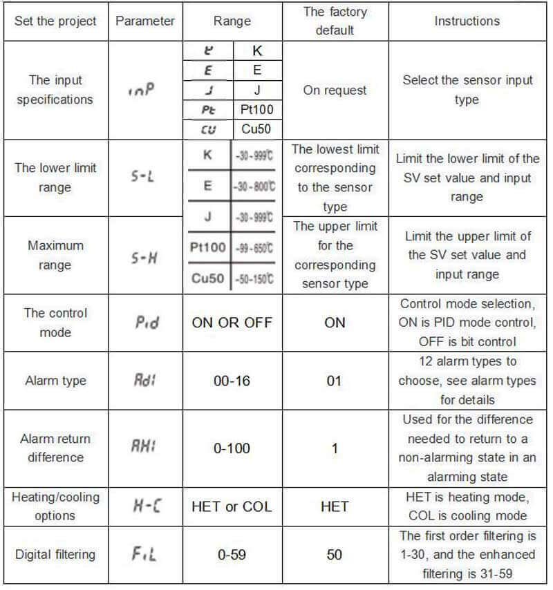
This function is used to correct temperature errors caused by external sensors, etc., but the controller itself is basically error free.
If the actual temperature is 80 ° C but the controller shows 78 ° C, then set the error correction [ ] to"
] to"  ", and the controller's display temperature will become 80℃.
※Setting range -99~99℃.
※After error correction, if current temperature (PV) is out of range " "or"
"or" " will be displayed.
6.Digital Filtering [ ]
]
Frequent changes of input signals lead to unstable display of current temperature (PV), which will affect the instability of the operation volume and thus lead to instability of the output. Therefore, this function is to filter the input signals to achieve stable control.
※1-30 is the first filtering, and 31-59 is the enhanced filtering.
※ Factory default setting is 50, suitable for most occasions, no special requirements without modification.
7.Alert type [ ]
]
|
The set value |
Alarm types |
Positive alarm value (AL1) |
Negative alarm value (-AL1) |
Deviation alarm/absolute alarm |
|
0 |
No alarm function |
NO Output |
|
|
|
1 |
Limit deviation |
|
|
Deviation alarm |
|
2 |
The lower limit deviation |
|
|
Deviation alarm |
|
3 |
Interval alarm |
|
Has been to OFF |
Deviation alarm |
|
4 |
Out-of-range alarm |
|
Has been to OFF |
Deviation alarm |
|
5 |
Absolute limit |
|
|
Absolute alarm |
|
6 |
Absolute lower limit |
|
|
Absolute alarm |
|
10 |
No alarm function |
NO Output |
|
|
|
11 |
Attached standby upper limit deviation |
|
|
Deviation alarm |
|
12 |
Attached standby lower limit deviation |
|
|
Deviation alarm |
|
13 |
Alarm in the standby range |
|
Has been to OFF |
Deviation alarm |
|
14 |
Alarm outside standby range attached |
|
Has been to OFF |
Deviation alarm |
|
15 |
Attached upper limit of standby absolute value |
|
|
Absolute alarm |
|
16 |
The lower absolute value of standby is attached |
|
|
Absolute alarm |
Use when you want to interact with the set temperature.
The alarm action point will change with the change of setting temperature.

No need to interact with the setting temperature.

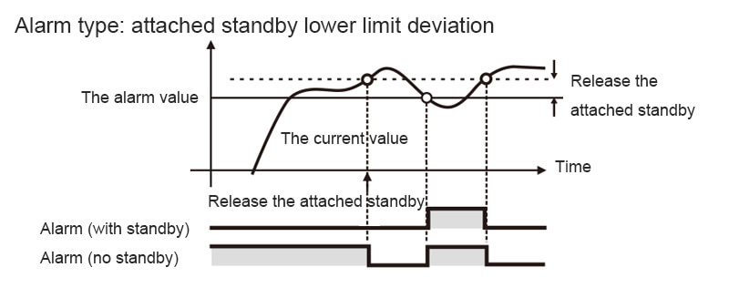
The attached standby function means that the alarm will not be ON even if the condition of "ON" is reached from the current value beyond the alarm range until it enters the next alarm range.
8.Alarm return difference [ ]
]
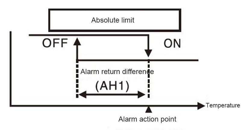
Used for the difference needed to return to a non-alarming state from an alarming state.
If the alarm action point is 120 ° C, the alarm return difference value is set at 20 ° C. When the temperature reaches above 120 ° C, it will be in the alarm state; when the temperature falls below 100 ° C, it will return to the non-alarm state.
※ The setting range is 0~100℃.
※ Factory default is 1℃
Fault message indication
|
Message |
Instructions |
Elimination method |
|
HHH |
Input disconnected or out of range |
Please check the input signal for error |
|
LLL |
Input disconnected or out of range |
Please check the input signal for error |
Matters needing attention
1.In order to eliminate inductive interference, please wire the product separately with high-voltage lines, power lines, etc.
2.Use the M3 terminal in the following shape.

3. Please use the power switch or circuit breaker when turning off the power to the product.
4. Please install the switch and circuit breaker nearby for the operator to operate.
5. If the product is used as temperature indication or adjustment, it should not be used as other instruments.
6. When using the thermal resistance (RTD) sensor, 3 wires should be connected. If you want to extend the wire, you must use the same type and length of wire connection.If the impedance of the line is different, it may cause temperature deviation.
7. When the power line and the input signal line have to be installed closer, please add a filter at the power end and shield the signal line.
8. Keep away from high frequency equipment (high frequency welder, high frequency sewing machine, high capacity SCR controller)
9. When the measurement input is switched on, HHH or LLL will be displayed if any error occurs. At this time, check whether the input is wrong after power off.
10.This product is used in the following environments.
①Indoor ②Pollution level 2
③Altitude 2000m below ④Installation classification LL
※ If you violate the above precautions, it may cause product failure. Please be sure to comply.
Product parameters
|
Power supply voltage |
①220VAC 50/60Hz ②100-240VAC/DC |
|
|
Range of allowable voltage variation |
90-110% of the supply voltage |
|
|
Consumed power |
Below 8VA |
|
|
The input specifications |
Thermocouple |
K E J |
|
Thermal resistance |
Pt100 Cu50 |
|
|
Display precision |
±0.5% |
|
|
The input specifications |
The relay 250VAC 5A is on and off |
|
|
Below SSR 12VDC±2V 20mA |
||
|
Analog voltage output (0-5V, 1-5V) |
||
|
Analog current output (0-20mA, 4-20mA) |
||
|
SCR Silicon controlled output (zero crossing output, phase shifting output) |
||
|
Alarm output |
The relay 250VAC 5A is one NO |
|
|
The control mode |
Bit control, PID control |
|
|
Sampling period |
100ms |
|
|
Relay life |
Mechanical more than 2.5 million times electrical more than 100,000 times |
|
|
Withstand voltage |
2000VAC 50/60Hz 1 min (between terminals and housing) |
|
|
Resistance to vibration |
5~55Hz(cycle 1 minute) amplitude 0.75mm X,Y,Z all directions for 2 hours |
|
|
Insulation impedance |
More than 10 om Ω MEGA (500 VDC) |
|
|
anti-interference |
Simulated square wave generator interference (pulse width 1 m) ±2KV R phase S phase |
|
|
Power failure memory |
About 10 years (non-volatile semiconductor memory) |
|
|
The surrounding environment |
Operating ambient temperature |
When stored at -5~40℃ :-10~50℃ |
|
Ambient humidity in use |
35 ~85% storage :35 ~85% |
|
Parameter Settings
1.All parameters
Parameter group lock setting range
|
0 |
Unlocked |
|
1 |
Lock parameter set 2 |
|
2 |
Lock parameter set 1,2 |
|
3 |
Lock parameter set 1,2 and SV |
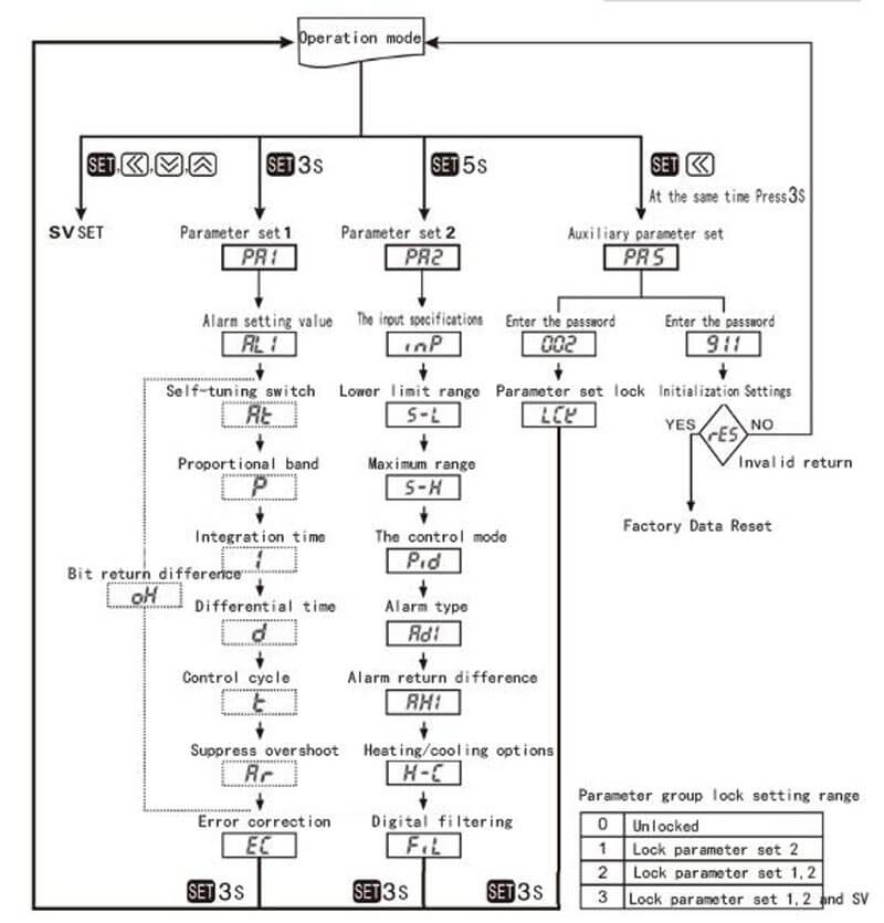
※In any parameter group, press the limit for 3 seconds, save the set value and return to operation mode.(SV setting, just press the key to return to operation mode once)
※ After entering the parameter setting mode, if no key is pressed within 30 seconds, the operation mode will be returned automatically. The changed parameters cannot be saved and the parameter values before the change are still maintained.
※Press to enter the next set of parameters.
※The parameter of the dotted line marker will be shown or hidden as control method is in the state of"
 "or"
"or" ".
".
※Parameters are correlated with each other. Please make sure to set them in the order of "Parameter group 2" → "Parameter Group 1" → "SV Setting".
※There are parameter group lock and parameter initialization functions in the auxiliary parameter group, please use with caution.
2.Parameter Group 2 [PA2]
3Parameter Group 1 [PA1]
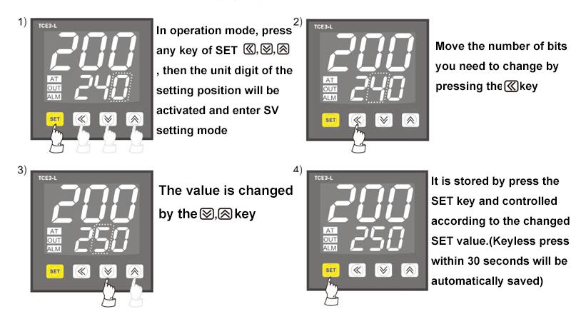
4.Set the SV
5.Parameter group lock
While holding down for 3 seconds, enter password 002 to enter parameter group lock [
 ].
].
※Parameter groups can be viewed when locked, but the lock setting range of parameter groups cannot be modified
Parameter group lock setting range
|
0 |
Unlocked |
|
1 |
Lock parameter set 2 |
|
2 |
Lock parameter set 1,2 |
|
3 |
Lock parameter set 1,2 and SV |
6.Parameter initialization
All parameters initialize factory Settings.At the same time, press and hold  for 3 seconds, enter password 911, and enter the initialization Settings[
 ]
]
When selected as " " the previous state will be returned; when selected as "
 " all parameters will be restored to factory Settings.